
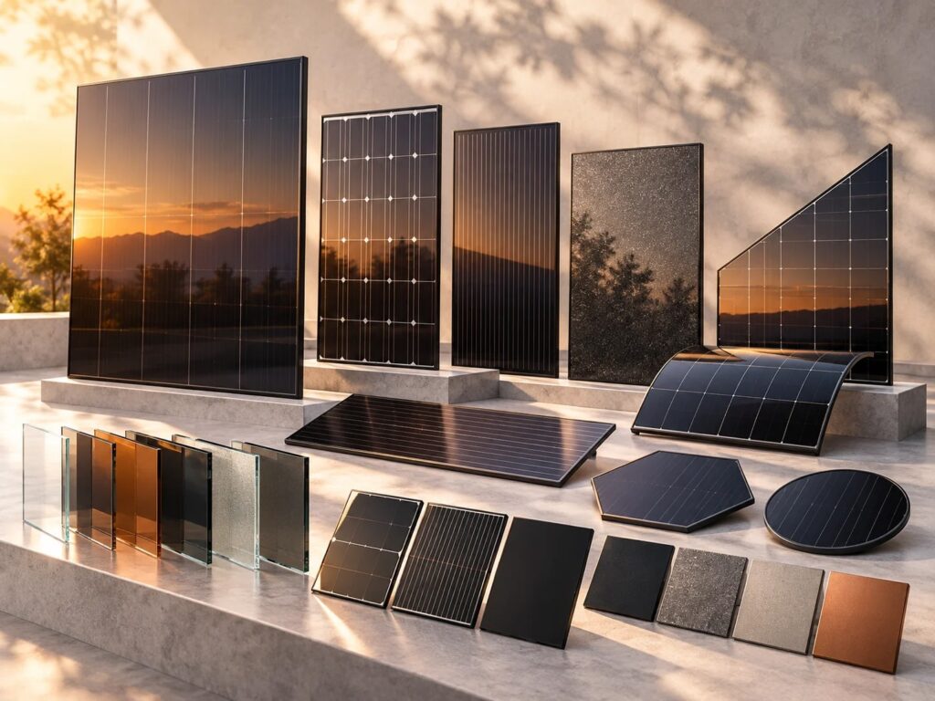
Cover visual: AI-generated concept illustration, not a completed project or certified product.
MODULE CONSTRUCTION · ENGINEERING GUIDE
Glass-Glass BIPV Module Design: What OEM Teams Need to Define
Glass-glass photovoltaic modules can be adapted to a range of building-integrated applications, but non-standard dimensions require careful coordination between the building product and module design. A chosen glass thickness or encapsulation material should never be treated as a standalone durability guarantee.
1. Start with the Building Interface
What supports the module? How does it connect to adjacent roof tiles or cladding? Does the installation include separate weatherproofing? Record the support positions, clamping zones, expected displacement, available rear clearance and any edge overlap requirements. The module manufacturer and building-system developer should agree where their responsibilities begin and end.
2. Define the Glass Construction
Document the front and rear glass thickness, surface treatment, color, tolerances and relevant safety requirements. Mechanical behavior depends not only on glass thickness but also on module dimensions, support layout, lamination and use conditions. Changes to any one element can affect the product’s validation needs.
3. Select Encapsulation and Edge Sealing
POE and EVA are examples of encapsulation materials used in photovoltaic manufacturing. For particular glass-glass constructions, moisture protection, adhesion, lamination process control and compatibility with other materials need evaluation. Additional edge sealing arrangements such as butyl-based materials may be considered, but must be qualified for the final assembly.
4. Account for the Cell Layout
Cell placement affects not only power output but also internal clearances and visible appearance. A change in external module size can require a different cell count, cell format or interconnection route. For architectural products, discuss visible borders, spacing, color consistency and cable exit positions early.
5. Plan Electrical Connections
Junction box size and location must suit the mounting system. Specify cable cross-section, net cable length, connector family and relevant electrical requirements. A component that is electrically acceptable may still be incompatible with the installation geometry.
6. Agree the Validation Route
Testing expectations depend on the module’s intended market and application. PV-module qualification and BIPV/building-system requirements are related but distinct. Consider the IEC 61215, IEC 61730 and IEC 63092 families as potentially relevant starting points and confirm current regional requirements with the project team.
Suggested Technical Package
- Dimensioned drawings and mounting details
- Glass specification and desired visual finish
- Preferred cell technology and electrical targets
- Encapsulation and edge requirements
- Junction box, wiring and connector specifications
- Prototype quantities, intended market and validation plan
For an OEM custom module assessment, explore FGNEX SOLAR’s custom BIPV components or contact the manufacturing team.